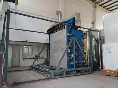
GV-JR-NJW-CE Vertical Loading Fire Resistance Test Furnace


Introduction
According to fire safety requirements, various components such as fire doors, windows, rolling shutters, fire-resistant glass, firewalls, non-load-bearing vertical partition elements, load-bearing vertical partition elements, and columns should undergo fire resistance limit testing. In accordance with the national standard GB/T 9978-2008, fire performance tests should use open-flame heating to subject the test specimens to conditions similar to those in actual fires. This test furnace simulates the actual temperature rise process during a fire, meeting the requirements for fire resistance limit testing and providing a comprehensive evaluation of the component’s fire performance.
Referenced Standards and Test Items
(1)ISO 834-1:2025 Fire-resistance tests — Elements of building construction Part 1: General requirements
(2)ISO 3009 Fire-resistance tests — Glazed elements
(3)ISO 3008-1:2025 Fire resistance tests — Door and shutter assemblies Part 1: General requirements
(4)GB/T 12513-2006: Fire Resistance Test Method for Glazed Components
(5)GB/T 7633-2008: Fire Resistance Test Method for Doors and Rolling Shutters
(6)GB 23864-2009: Fireproof Sealing Materials
(7)GB 28376-2012: Tunnel Fire Protection Panels
(8)GB/T 23451-2009: Lightweight Partition Strips and Panels for Buildings
(9)GA/T 714-2007: Rapid Heating Fire Resistance Test Method for Fire Protection Materials of Components
(10)GB/T 9978.1-2008: Fire Resistance Test Methods for Building Components – Part 1: General Requirements
(11)GB/T 9978.2-2019: Fire Resistance Test Methods for Building Components – Part 2: Guide for Measuring Fire Exposure Uniformity of Test Specimens
(12)GB/T 9978.3-2008: Fire Resistance Test Methods for Building Components – Part 3: Test Methods and Application Notes for Test Data
(13)GB/T 9978.4-2008: Fire Resistance Test Methods for Building Components – Part 4: Special Requirements for Load-Bearing Vertical Partition Elements
(14)GB/T 9978.7-2008: Fire Resistance Test Methods for Building Components – Part 7: Special Requirements for Columns
(15)GB/T 9978.8-2008: Fire Resistance Test Methods for Building Components – Part 8: Special Requirements for Non-Load-Bearing Vertical Partition Elements
(16)GB/T 9978.10-2008: Fire Resistance Test Methods for Building Components – Part 10: Special Requirements for Curtain Walls
Technical Parameters
Parameter | Specification |
Furnace Type | Vertical Component Fire Resistance Test Furnace |
Furnace Chamber Dimensions | 4.0 m × 4.0 m × 1.5 m |
Fuel | Natural Gas |
Maximum Operating Temperature | 1300 °C |
Number of Burners | 10 sets |
Total Gas Consumption | ≤ 200 m³/h |
Exhaust Gas Temperature | < 180 °C |
Exhaust Air Volume | ≈ 20,000 m³/h |
Furnace Wall Temperature | < 45 °C |
Insulation Material | Internal lining contains zirconia wool blocks |
Thermocouples | 16 inside the furnace; 30 on the back-fire surface |
Movable Thermocouple: 1
Ambient Thermocouple: 1
The thermocouples comply with GB/T 16839.1 and are 2 mm diameter nickel-chromium/nickel-silicon (Type K) thermocouples. They are sheathed in heat-resistant ceramic tubes with heat-resistant ceramic rings packed inside, and the measuring junction extends at least 25 mm beyond the sheath.
Furnace Thermocouples: Temperature range 0 °C – 1300 °C, accuracy ±15 °C
Back-Fire Surface Thermocouples: Type K nickel-chromium/nickel-silicon thermocouples, temperature range 0 °C – 800 °C, measurement accuracy better than ±4 °C
Movable Thermocouple: Temperature range 0 °C – 900 °C, measurement accuracy better than ±4 °C
Ambient Temperature Thermocouple: Temperature range –10 °C – 100 °C, accuracy better than ±1 °C
Furnace Rear Wall: 4 thermocouples
Observation Window:
Combustion Control Type: Proportional combustion, automatic furnace pressure control, automatic temperature regulation, temperature curve programmed control, computer-assisted management
Exhaust Method: Mechanical exhaust at the back
Computer Configuration: Tsinghua Tongfang; CPU: Intel dual-core processor 3.0 GHz or higher; Memory: ≥ 4 GB; Hard Drive: ≥ 500 GB; Monitor: ≥ 19-inch LCD; Dedicated graphics card ≥ 512 MB compatible with the video acquisition system; Includes licensed operating system and licensed Microsoft Office software
List of Main Components and Equipment Configuration of the System
Serial Number | Name | Quantity |
ⅠFurnace Body | ||
1 | Furnace body | a set |
2 | Furnace cover | a set |
3 | Sealing plate | a set |
Ⅱ Gas Main Pipeline | ||
4 | Ball valve | 1 |
5 | Pressure gauge | 1 |
6 | High-pressure PTFE gasket | 1 |
7 | Gas pipeline | a set |
8 | Gas pipeline | a set |
9 | Ball valve | 6 |
10 | Gas filter | 1 |
11 | Gas pressure reducing valve | 1 |
12 | Automatic vent valve | 1 |
13 | High-pressure manometer | 1 |
14 | Low-pressure manometer | 1 |
15 | Manometer switch | 1 |
16 | Pressure switch | 1 |
17 | Gas solenoid valve | 1 |
18 | Gas overpressure safety shut-off regulator | 1 |
19 | Pressure gauge | 1 |
Ⅲ Integrated Burner | ||
20 | Integrated Burner | 10 |
21 | Fan | 10 |
22 | Solenoid Valve | 20 |
23 | Controller | 10 |
24 | Igniter | 10 |
25 | Flame Detector | 10 |
26 | Air Pressure Sensor | 10 |
27 | Proportional Motor | 10 |
28 | Proportional Valve | 10 |
Ⅳ Refractory materials | ||
29 | Zirconia Fiber Blanket | a set |
30 | Refractory Mortar | a set |
31 | Sight Hole Prefabricated Component | 4 |
32 | Flue Outlet Prefabricated Component | 2 |
33 | Silica Cover Plate | a set |
34 | Kiln Mouth Cotton Blocks | a set |
35 | Cotton Blocks for Flue | a set |
36 | Fasteners and Auxiliary Materials | a set |
Ⅴ Smoke exhaust system | ||
37 | Exhaust Duct | a set |
38 | Exhaust Fan | 2 |
39 | Smoke Hood | 2 |
Ⅵ control system | ||
40 | Computer | a set |
41 | Monitor | a set |
42 | Molded Case Circuit Breaker | 1 |
43 | Circuit Breaker | 12 |
44 | Contactor | 12 |
45 | Thermal Relay | 10 |
46 | Frequency Converter | 1 |
47 | Lockable Emergency Stop Button | 1 |
48 | Selector Switch | 1 |
49 | Key Switch | 1 |
50 | Red Button | 5 |
51 | Green Button KW | 5 |
52 | Red Indicator Light | 2 |
53 | Green Indicator Light | 2 |
54 | Alarm Light | 1 |
55 | Buzzer | 1 |
56 | Relay | 60 sets |
57 | Switching Power Supply | 1 |
58 | PLC Main Unit | 1 |
59 | 8AD Module | 2 |
60 | 4DA Module | 3 |
61 | Communication Module | 1 |
62 | Backfire Surface Data Acquisition Instrument | 4 |
Ⅶ Specimen frame | ||
63 | Load-Bearing Specimen Frame | 1 |
64 | Wall Loading System | 1 |
65 | Column Loading System | 1 |
Ⅷ Temperature and pressure monitoring | ||
66 | K-Type Thermocouple | 16 |
67 | Backfire Surface Thermocouple | 30 |
68 | Movable Thermocouple | 1 |
69 | Ambient Thermocouple | 1 |
70 | Pressure Sensor | 3 |
Ⅸ mobile app | ||
71 | Remote Mobile App | 1 |
Ⅹ Monitoring system | ||
72 | Monitoring System | 1 |
Note: The specific model is subject to the actual configuration. The actual use shall not be lower than the configuration in this table.
Leave Message Get Price