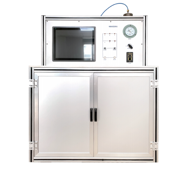
Test Bench for Car Door Locks and Hinges


This test bench is mainly used to perform simulated durability tests on car door hinges and door locks of passenger cars, SUVs, and MPVs under normal temperature conditions. The tests are designed to inspect the functional quality of vehicle side door locks and hinges.
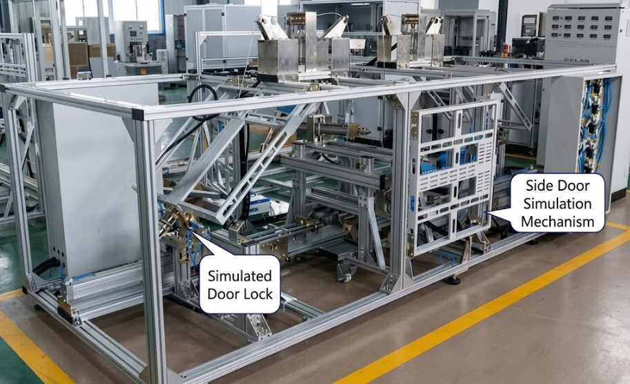
The test bench primarily consists of two parts, including the door lock and hinge durability simulation mechanism. It is capable of simulating the durability of a single car door.
For customer convenience, the bench is equipped with two sets of door durability mechanisms, allowing tests to be conducted on either one door or two doors simultaneously.
Standards
(1) QC/T 323-2007 – "Automotive Door Locks and Door Retainers"
(2) GB 15086-2006 – "Performance Requirements and Test Methods for Automotive Door Locks and Door Retainers"
(3) QC/T 627-1999 – "Automotive Power Door Lock Systems"
The technical specifications of this test bench comply with the relevant testing requirements outlined in the above standards.
Technical Description
1. Test Items
1.1 Unlocking, opening, and closing of the side door
1.2 Durability test of door hinges
2. Main Components of the Test Bench
The test bench is mainly composed of the following components:Simulated Vehicle Door Lock and Hinge Mechanism ,Computer Control System ,Electrical Control Cabinet ,Test Installation Frame ,Door Durability Test Module,Rear Hatch Durability Test Module System Software .The simulated doors and rear hatch are made of carbon steel welded parts with a powder-coated surface finish. One end of the door is mounted with real vehicle hinges fixed to an aluminum frame, while the other end is mounted with the door lock or latch, also fixed on an aluminum profile frame, ensuring both durability test stability and ease of adjustment.
The control cabinet uses a steel frame structure, with the electrical control section integrated but independent from the test bench. The layout of all components is compact and reasonable, providing a user-friendly interface.
The computer host is embedded within the operation console but can also be placed separately. Both the control cabinet and the base of the test bench are equipped with casters, allowing for easy mobility.
The equipment features an elegant and refined overall appearance. Inside the control cabinet, all electrical wiring is standardized and neatly arranged. Pneumatic pipes and related components are clearly labeled, ensuring easy identification. External connections use aviation connectors for communication with the cabinet. The pneumatic layout is well-organized and clearly marked, making operation convenient.
During durability testing, the system can automatically determine whether functions are operating normally. If an abnormality is detected, an alarm is triggered and the test is stopped. The test bench utilizes an advanced flexible system platform with a modular design, allowing certain functions to be expanded or removed according to operational requirements.
Detailed Description of the Test Bench
3.1 Composition and Functions of the Test Bench
The test bench is mainly composed of the simulated vehicle door lock and hinge mechanism, computer control system, electrical control cabinet, test installation frame, door durability test module, and Xiongqiang system software.
The structure is based on aluminum profile framing, allowing all actuators and testing mechanisms to be conveniently mounted on the simulated vehicle body.
Through the test control system, the operator can select and execute predefined test actions and procedures, including manual durability tests or automatic durability tests.
Electrical components communicate with the computer via shielded cable connectors.
Each test section includes automatic counting. During testing, the system can automatically monitor, control, and record all parameters and data of the tested specimens. It can automatically determine whether functions are normal; if any abnormality occurs, an alarm is triggered and the test stops. Unnecessary parameters can be disabled from monitoring.
The system supports 24-hour unattended operation. In the event of a sudden power failure, all test information is automatically saved, allowing the test to resume from the point of interruption when power is restored.
The test action frequency can be adjusted according to requirements.
The human-machine interface (HMI) is fully localized in Chinese and supports editable combination action tests, facilitating complex test sequences.
Durability test cycle count can be set in the range of 1 to 999,999 cycles.
3.2 Installation Platform
The platform is used for mounting simulated doors, latches, side doors, and rear hatch locks.
The main structure is assembled from industrial profiles and reinforced with stiffening ribs, making it sturdy, aesthetically pleasing, lightweight, and flexible for adjusting to different types of door lock tests.
Simulated doors are constructed from welded steel components or aluminum profiles.
The bottom of the platform is equipped with shock absorbers to reduce impact during testing, and casters are installed for easy mobility.
3.3 Dual Simulated Door Durability Test Module
The simulated doors are made of welded components with a powder-coated surface finish. One end is mounted with real vehicle hinges fixed to the frame, while the other end is equipped with a door lock or latch.
3.3.1 Dual Side Doors
Dimensions: 750 × 750 mm (subject to actual design)
Base weight: ≤16 kg (including door lock operating mechanism and various fixtures mounted on the door)
Configurable counterweight blocks: two 5 kg blocks, two 2 kg blocks
Counterweights are adjustable within a 300 × 300 mm range
3.3.2 Dual Door Closing Mechanisms
Each door is actuated by SMC cylinders to open or close the simulated door.
Limit mechanisms adjust the door opening angle.
Throttle valves regulate the speed of the pneumatic cylinders for various actions, while air pressure calibration controls the pushing/pulling force of each cylinder.
Specifications:
Door closing speed: 0–2 m/s (adjustable)
Test frequency: 0–8 cycles/min (adjustable)
Door opening angle: 0–80° (adjustable)
3.3.3Dual Unlocking Mechanisms
For each side door, two cylinders are used per lock to perform the unlocking operation.
Control System
Computer Control Section
1. Hardware Configuration
Computer System
Yanzhuang Industrial Control Computer: P4 3.0GHz / 1GB RAM / 160GB HDD
19-inch LCD Monitor
Motion Detection Board
Data Acquisition Board
Drawer-type Keyboard Tray
2. Pneumatic System
Pneumatic Control Cabinet,A separate pneumatic control cabinet independently controls and drives the motion of each door-opening mechanism.
The pneumatic layout is well-organized, standardized, and clearly labeled.
Pneumatic pipelines inside the test bench, as well as those connecting the test bench to the control system, are protected by metal cable trays, ensuring both equipment reliability and an aesthetically clean appearance.
3.Electrical Control Cabinet
A separate electrical control cabinet is provided.
All electrical system control and signal wiring is reasonably arranged, standardized, and clearly labeled.
All connection ports are easily detachable, facilitating maintenance and repair.
4.Control and Data Processing Software
The test bench software is developed on the Windows XP operating platform, offering user-friendly operation.
The software allows setting of working time, test cycle count, and low-pressure alarms.
1) Model Management Module
Users can add or delete a product model for a specific vehicle type.
The test management program has two access levels:
Operator: Can only perform test-related operations.
Administrator: Can modify and confirm product models, product parameters, durability cycle counts, and other relevant settings.
2) Test Action Module
Allows editing of product test actions, including parameters such as door opening, closing, and pause times.
Users can combine different actions to create various test sequences suitable for different vehicle types’ durability tests.
For door durability tests, actions such as unlocking, opening, and closing can be edited and input.
3) Test Parameter Module
Enables setting of test cycle counts, door opening/closing failure counts, and other test parameters.
Allows configuration of action pause times and detection parameters for front hood or door closure position.
4) System Function Module
Includes system management, print functions, and the ability to modify related test report content and print test reports.
Test data is automatically saved, and can be exported to Excel.
A database is provided to store measured data for easy querying and retrieval.
5) Fault Alarm Module
The test bench is equipped with self-diagnosis and alarm functions.
If a system fault occurs, the system will trigger an alarm and automatically stop the test.
During testing, if any cylinder fails to perform its intended action within the set time, an alarm signal is issued, and the system indicates the location of the fault.
Technical Specifications of the Test Bench
1. Mechanical Performance
Test frequency: 1–8 cycles/min, adjustable by modifying test steps and pause times.
Side door opening angle: 0–80°, adjustable according to different vehicle models.
Test actions include: Unlocking (mechanical or pneumatic) → Door opening → Door closing.
Durability test cycle range: 1–999,999 cycles.
2. Operating Conditions
Ambient temperature: 0℃ to 40℃
Relative humidity: 20%–85% RH
Power supply: AC 220V ±10%, 50Hz ±2%
Air supply pressure: 0.6–0.8 MPa
Leave Message Get Price