Bunched Cable Vertical Flame Propagation Tester


This bunched wire and cable vertical flame propagation test apparatus is manufactured in strict accordance with GB/T 18380.31-2022, which is equivalent to IEC 60332-3-10:2000. It is used to evaluate the ability of vertically installed bunched wires, cables, or optical cables to resist vertical flame spread under specified conditions. The equipment is economical, practical, and widely used in the wire and cable industry.
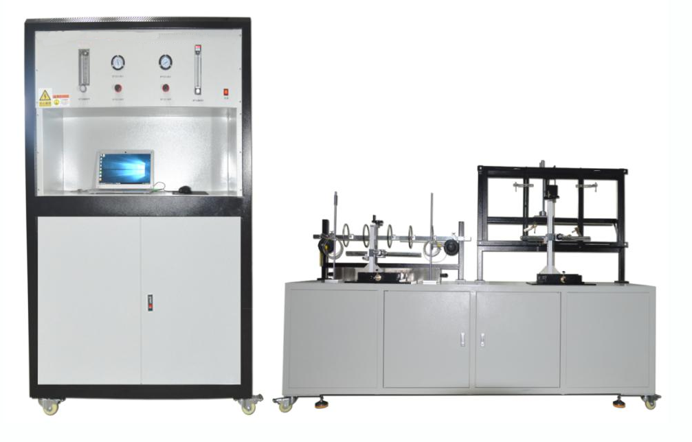
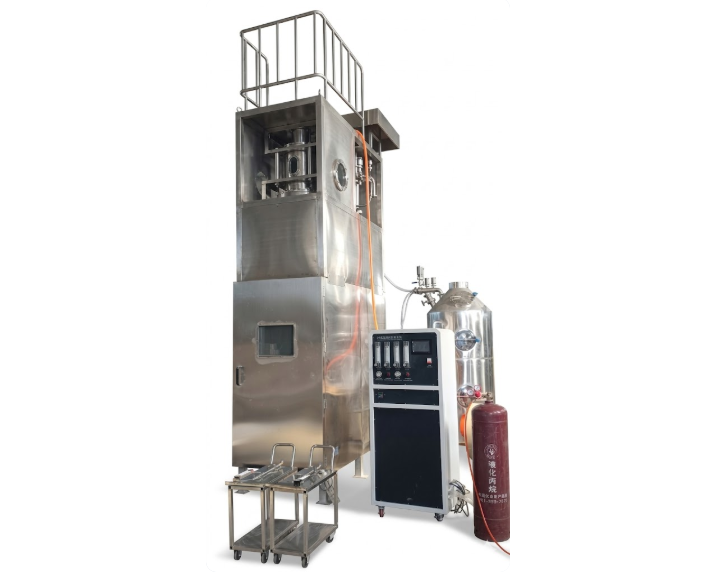
The test apparatus consists of a self-supporting chamber with dimensions of 2500 mm (length) × 3200 mm (width) × 4500 mm (height), with the bottom elevated above the ground. The chamber is sealed on all sides. Air enters through an 800 mm × 400 mm air inlet opening located 150 mm from the front wall at the bottom. An exhaust outlet of 300 mm × 1000 mm is located at the upper rear of the chamber.
The rear wall and both side walls are constructed using thermal insulation materials with a heat transfer coefficient of approximately 0.7 W·m⁻²·K⁻¹. The distance between the steel ladder and the rear wall is 150 mm. The lowest rung of the steel ladder is 400 mm above the ground, and the lowest point of the cable specimen is approximately 100 mm above the ground.
Technical Specifications
1. Combustion Chamber Section
(1) Overall Dimensions
2500 mm (L) × 3200 mm (W) × 4500 mm (H)
(2) Material
Thermally insulated structure with a heat transfer coefficient of 0.7 W·m⁻²·K⁻¹, consisting of stainless steel plates lined with 65 mm thick mineral fiber insulation
(3) Air Supply System
Controls the airflow through the chamber at (5000 ± 500) L/min
Ensures stable airflow velocity during testing
Air inlet duct cross-sectional area: approximately 240 cm², with a length greater than 60 cm
Equipped with a spray extinguishing device for forced flame suppression after testing
(4) Steel Ladder Types
Standard steel ladder: width 500 mm
Wide steel ladder: width 800 mm
(5) Emission Purification System
The chamber is equipped with a smoke collection and scrubbing system that does not affect the airflow through the chamber.
(6) Ignition Source
The ignition source consists of one or two ribbon-type propane gas burners, each equipped with a flow meter and a Venturi mixer.
The burner surface is a flat metal plate drilled with 242 holes, each with a diameter of 1.32 mm. The holes are spaced 3.2 mm center-to-center, arranged in three staggered rows containing 81, 80, and 81 holes, respectively, within a nominal area of 257 mm × 4.5 mm.
Additionally, a row of small guide holes is provided on each side of the burner plate to stabilize the flame.
a) Each burner is equipped with a rotameter to accurately control propane and air flow rates.
b) Under reference conditions of 100 kPa and 20°C, the gas flow rates are:
Air: (77.7 ± 4.8) L/min
Propane: (13.5 ± 0.5) L/min
(7) Ignition Source Position
The burner is placed horizontally
Distance from the front surface of the cable specimen: (75 ± 5) mm
Distance from the bottom of the chamber: (630 ± 5) mm
Positioned symmetrically with respect to the axis of the steel ladder
The flame application point is located at the center between two ladder rungs and at least 500 mm above the lower end of the specimen
(8)Observation Window
One tempered glass observation window, framed with stainless steel
(9) Exhaust System
Equipped with two centrifugal exhaust fans
Sealing sliding plate made of 2.0 mm stainless steel
(10) Air Inlet
Quantity: 1
Diameter: Φ160 mm
(11) Bottom Support Frame
Constructed using 40 mm × 40 mm square steel tubing
2. Control System
Description:
(1) Air Flow Adjustment:Adjusts the airflow rate for the test. Under reference conditions of 100 kPa and 20°C, the airflow is approximately 77.7 L/min.
(2) Gas Flow Adjustment:Adjusts the gas flow rate for the test. Under reference conditions of 100 kPa and 20°C, the gas flow is approximately 13.5 L/min.
(3) Air Pressure Display:Displays the air pressure during the test.
(4) Gas Pressure Display:Displays the gas pressure during the test.
(5) Air Pressure Regulation:Adjusts the inlet air pressure.
(6) Gas Pressure Regulation:Adjusts the inlet gas pressure.
(7) Temperature Display:Displays the monitored test temperature.
(8) Chamber Temperature Display:Displays the internal temperature of the combustion chamber.
(9) Burning Time:The flame application time is set according to standard requirements. Once ignition starts, timing begins immediately. When the preset burning time is reached, the system automatically switches to the after-flame timing mode. The timing range can be freely set from 0 to 99.99 s/min/h.
(10) After-Flame Time:After the burning time ends, the after-flame timer starts automatically and continues until the flame on the specimen extinguishes naturally, with no falling debris or visible flame remaining. Press the “After-Flame Pause” button to freeze the displayed time, which is recorded as the after-flame time.
(11) After-Flame Pause:Pressing this button will freeze the after-flame timer at the current moment.
(12) Ignition:After setting the required burning time, press the “Ignition” button. The igniter activates, igniting the burner, and the flame is applied to the specimen to start combustion.
(13) Stop:Press the “Stop” button to extinguish the burner flame, and all timers will reset.
(14) Power Supply:The power supply is AC 220V, 50 Hz. Connect the power cord and switch on the power to start the instrument.
(15) Circulating Water Pump:Press the “Circulating Water Pump” button to activate the pump, enabling the water tower to perform exhaust gas filtration.
(16) Fan:Activates the exhaust fan.
(17) Single/Double Burner Selection:Switches between single-burner and dual-burner operation modes.
3.Test Section
(1) Combustion Test Chamber:2000 mm (L) × 1000 mm (W) × 4000 mm (H)
(2) Ribbon-Type Propane Gas Burners:2 units (as shown in the figure)
(3) Steel Ladders:Standard type: width 500 mmWide type: width 800 mm
(4) Water Pump:1 unit, 370 W single-phase pump
(5) Inner Flame Contact Point Gauge:1 unit
(6) Paper Dimension Measuring Gauge:1 unit
(7) Test Length Measuring Ruler:1 unit
(8) Test Fixture:Material: finely machined steel plate with baked paint finish,Color: pure black
Precautions
Before the Test:
Connect the hose from the liquefied petroleum gas (LPG) cylinder with a pressure regulator, then connect the signal control lines. Switch on the control box power and check that all connections are correct. Pay special attention to whether there is any gas leakage.
Only after confirming that there is no leakage should the power switch be turned on. Open the main valve of the gas cylinder and adjust the pressure regulator. The high-pressure gauge of the acetylene regulator should indicate a pressure of 0.01–0.02 MPa (this is the working outlet pressure). If it exceeds 0.02 MPa, it may be dangerous and could indicate leakage.
After the Test:Turn off the power switch and close the main valve of the gas cylinder. Ensure that there are no remaining flames or smoldering materials before leaving the test area.
FAQ
1.What is a Bunched Cable Vertical Flame Propagation Tester?
A Bunched Cable Vertical Flame Propagation Tester is a specialized device used to evaluate the fire performance of bunched cables under vertical flame conditions. This tester simulates potential fire hazards in environments where these cables are installed, helping to assess how quickly flames spread along the cables and how much smoke and toxic gases are produced. Such testing is crucial for ensuring compliance with safety standards and regulations.
2.Why is it important to test bunched cables for flame propagation?
Testing bunched cables for flame propagation is vital for preventing fire hazards in residential, commercial, and industrial settings. These tests help manufacturers and safety regulators ensure that cables meet required safety standards, reducing the risk of fire-related incidents. Furthermore, understanding how flames propagate along bunched cables can inform the design of fire safety systems and improve overall building safety.
3.What standards are used in bunched cable vertical flame propagation testing?
Several international standards guide the testing of bunched cables for vertical flame propagation, including IEC 60332-1 and UL 1666. These standards outline the methodologies for assessing the flame spread characteristics of cables, ensuring that they are subjected to rigorous testing under controlled conditions. Compliance with these standards is essential for manufacturers looking to demonstrate the safety and reliability of their products.
4.How are bunched cable flame propagation tests conducted?
Bunched cable flame propagation tests are conducted by arranging cables in a specified bunching configuration and exposing them to an open flame from below. The setup involves careful measurement of flame height, spread rate, and any smoke or gas emissions during the test. The results are analyzed to determine the cable's performance in terms of flame spread, which is crucial for assessing fire risks in real-world installations.
5.What are the benefits of using a Bunched Cable Vertical Flame Propagation Tester?
Using a Bunched Cable Vertical Flame Propagation Tester provides several benefits, including the ability to comply with safety regulations, improve product design, and enhance fire safety in installations. It allows manufacturers to identify potential fire hazards associated with their cables and take corrective actions. Additionally, this testing helps instill confidence in consumers and professionals about the safety of electrical installations.
6.Who should perform the flame propagation testing?
Flame propagation testing of bunched cables should be performed by qualified professionals or laboratories that have experience in fire safety testing. These experts are knowledgeable in the relevant standards and methodologies, ensuring that tests are conducted accurately and reliably. Engaging accredited testing facilities can also help manufacturers achieve the necessary certifications for their products, facilitating market acceptance.
Leave Message Get Price