The working principle of current sensor
Current sensors are the core components used to detect current in industrial and electronic systems, and their working principles are diverse. The following is a step-by-step analysis of the mainstream technologies:
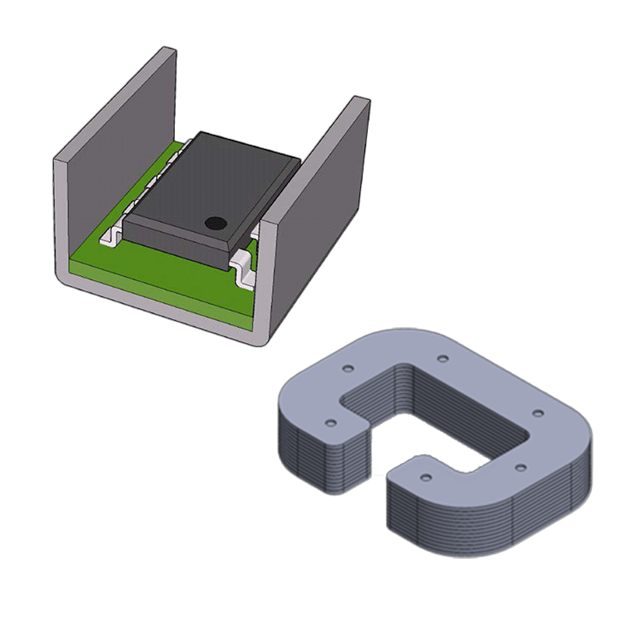
1. Hall effect sensor
Principle: Based on the interaction of magnetic field and current carrying conductor
Magnetic field generation: When the measured current (Iₚ) passes through the wire, a ring magnetic field (B) is generated around it.
Hall element detection: When the Hall plate is placed in a magnetic field and the current (Iₕ) passes through the Hall plate, the electrons are deflected by the Lorentz force to form a transverse voltage (Vₕ)。
Signal conversion: Vₕ is proportional to B (i.e. Iₚ), and the amplified circuit outputs a standard signal (such as 4-20mA or 0-5V)。
Features:
Isolation measurement: Electrical isolation, suitable for high voltage scenarios.
Wide frequency band: suitable for DC, AC and pulse current.
Limitations: Accuracy is affected by temperature and mechanical stress.
2.Fluxgate sensor
Principle: Use the non-linearity of magnetic properties of magnetic materials
Excitation magnetic field: The coil applies a high-frequency alternating magnetic field (H₀) to saturate the magnetic core periodically.
External field modulation: The magnetic field (H₁) generated by the measured current (Iₚ) changes the saturation point of the core.
Induced voltage analysis: The secondary coil detects the induced voltage caused by the change of magnetic core permeability, and obtains the value Iₚ by demodulation.
Features:
High precision: resolution up to 0.1mA, excellent linearity.
Anti-interference: insensitive to external magnetic fields.
High cost: Complex circuits and magnetic materials increase the cost.
3.Resistance shunt
Principle: Ohm's law of direct measurement
Low resistance series: precision resistance (Rₛ) in series in the circuit, the voltage at both ends Vₛ=Iₚ×Rₛ。
Signal amplification: the differential amplifier extracts Vₛ and converts it to standard output.
Features:
Simple structure: no magnetic core, low cost.
No isolation: need to be in common with the circuit under test, not suitable for high voltage.
High-frequency limitation: Inductance effects affect the high-frequency response.
4. Optical Fiber Sensor (FOCS)
Principle: Faraday magneto-optical effect
Magnetic field action: The magnetic field generated by the current (Iₚ) rotates the polarization plane of the light wave in the fiber.
Light intensity detection: by detecting the polarization change Angle, calculate the value of Iₚ。
Features:
High insulation: No electrical connection, suitable for extreme environments.
Anti-electromagnetic interference: Optical fiber transmission is not affected by electromagnetic noise.
High cost: Applicable to special scenarios such as HVDC power transmission.
5. Giant Magnetoresistance (GMR) sensor
Principle: The resistance of magnetic materials changes with the magnetic field
Magnetic field detection: The GMR chip senses the magnetic field generated by the current (Iₚ)。
Resistance variation: The magnetic field strength has a nonlinear relationship with the GMR resistance.
Signal processing: Output current values through linearized circuits.
Features:
High sensitivity: suitable for weak magnetic field detection.
Low power consumption: Nanoscale materials reduce energy consumption.
Temperature sensitive: need temperature compensation circuit.
Application scenario comparison
Type Applicable Scenario Accuracy isolation cost
Hall effect industrial power supply, inverter medium high
Fluxgate laboratory calibration, precision instruments Gao Gao
Resistor shunt Low voltage battery monitoring, consumer electronics low none extremely low
Fiber optic sensor HVDC transmission, nuclear power plant high extremely high
GMR sensors Automotive electronics, iot sensors medium high medium medium
Selection suggestion
In high voltage/high frequency scenarios, Hall effect or optical fiber sensors are preferred.
Precision priority: fluxgate or closed-loop Hall sensor.
Cost sensitive: resistive shunt or open loop Hall sensor.
Isolation requirement: Avoid resistor shunt.
By matching specific requirements, sensor performance and cost effectiveness are maximized.
2025-03-20 15:09
- Related News
VP-TEST-5000: Transpiration Analyzer for Textiles
DPL-2000: Steady-State Thermal Conductivity Tester
HTC-3000: Thermal Conductivity Analyzer for Extreme Environments
Flammability Analyzer by Oxygen Index
TRACKING-8000: Electrical Insulation Tracking Analyzer
MELTINDEX-3000: Polymer Flow Rate Analyzer
Color Fastness Tester Resistant to Scrub
CHRYSLER-BEND-5000: Automotive Component Flexibility Analyzer